FALL EDITION, 2015
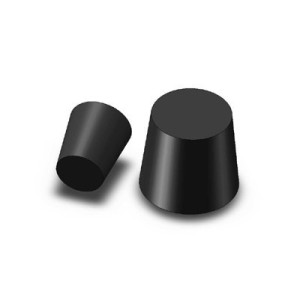
 Often we have a great idea for a new part, but are unsure about how to make that idea reality. The last newsletter detailed some of the advantages and hype about 3D printing. This newsletter goes into detail about the mechanics of going from idea to part. We recently used out Fusion3 3D printer to make a jig to hold a lab stopper to waterjet cut the center out. In the past we have struggled to hold the conical shaped rubber stoppers with cylindrical jigs we made using our waterjet.
 IDEA INTO CAD
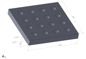
Every part that is designed and created needs to be defined and solve a problem. Often we think about the whole shape, but more advanced software and manufacturing allows us to focus on what is the function of the part and not on the mechanics of making it. For our stopper jig, we need to hold the stopper securely and repeatedly. Our old cylindrical jig allowed too much movement of the stopper while cutting. Therefore, we looked up the dimensions for the stopper, bottom diameter of .71”, top diameter of .94”, and height of .98”. Using 3D modeling software, these dimensions were used to make a multi-cavity jig. The cavities are symmetrical to allow the jig to be used in any orientation. A similar 2D CAD drawing was made with the same cavity locations for the waterjet cutting program to cut the holes.
SLICE THAT MODEL
The 3D model is then imported into software designed to “slice” the model into multiple layers. Essentially creating multiple 2D layers that add up to a full 3D model. Our Fusion3 3D printer uses a .2mm (about .008”) layer, so our 1” thick model requires over 125 2D layers to be printed. The parameters of the print are fine-tuned at this stage, speed, material, infill percentage, support arches, etc. More about this next issue.
PRINT YOUR PART
The printer then prints an initial layer onto a glass base (glass is used because it is flat and holds the heat to keep the plastic from contracting.) The head moves around extruding molten plastic onto the bed. After the first layer is printed, the bed drops on layer (.2mm) and the second layer is printed. This continues for each layer until the part is done.
 DETAILS, DETAILS
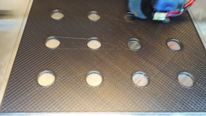
One of the great things about additive manufacturing is that less material means less time and money, unlike cutting, where more holes means more time and money. In figure 4, you can see the internal structure of our part is honeycombed. We used a 15% infill percentage for this print, meaning that the bottom, edges, and top are solid and all the inside of the part are 85% air. Parameters can be tweaked to balance time, cost, weight, and strength.
FINISHED PART
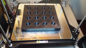
After printing our jig, the 3D printer returns to origin and cools off. You can see the glass table with a thin glue layer to help the part stay anchored to the bed.
In the next newsletter we will discuss some design considerations for 3D printing and waterjet and laser cutting. Check out our redesigned website, www.exactcut.net that has some of our coolest cuts of the week.